一、介绍
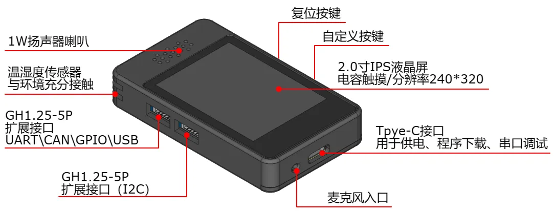
立创·实战派是嘉立创推出的一款带有屏幕、外壳的开发板,主控芯片是 ESP32-C3,外置 8MB FLASH,详见立创·实战派。
二、编译
此处使用 Ubuntu22.04 (WSL) 进行编译操作,需保证有良好的国际网络互联条件。
(一)设置开发环境
- 安装必要工具和库
确保你安装了 Python、Git 以及其他必需的工具(相关的编译器和工具链),当然后面操作中提示缺什么再装也来得及,这一步可以跳过。
- 配置 ESP-IDF 环境
克隆 ESP-IDF 仓库,初始化和安装所需的子模块和依赖,设置环境变量:
mkdir esp
cd esp
git clone --branch v5.1.2 https://github.com/espressif/esp-idf.git
cd esp-idf
git submodule update --init --recursive
./install.sh
source export.sh
(二)获取 MicroPython 源代码
从 GitHub 上克隆 MicroPython 的源代码仓库:
cd ~/esp
git clone https://github.com/micropython/micropython.git
(三)编译 MicroPython
- 编译
mpy-cross:
这是 MicroPython 的字节码编译器,用于将 Python 代码编译成字节码。
cd micropython
make -C mpy-cross- 编译 MicroPython 固件:
进入对应的端口目录(即 ports/esp32),编译 MicroPython 固件。
cd ports/esp32
make submodules
make
此时如果在 ~/esp/micropython/ports/esp32/build-ESP32_GENERIC 目录下可以看到一个名为 firmware.bin 的固件,继续下面的操作。
(四)定制和添加功能
- 添加显示驱动
此块屏幕应使用 ST7789 驱动。
cd ~/esp
git clone https://github.com/russhughes/st7789_mpy.git- 修改源代码
实战派外置 8MB FLASH、支持麦克风和扬声器,因此要对 MicroPython 源码做以下修改:
- 修改
~/esp/micropython/ports/esp32/boards/下的sdkconfig.base的 94~97 行:
修改前:
# For cmake build
CONFIG_ESPTOOLPY_FLASHSIZE_4MB=y
CONFIG_PARTITION_TABLE_CUSTOM=y
CONFIG_PARTITION_TABLE_CUSTOM_FILENAME="partitions-4MiB.csv"
修改后:
# For cmake build
CONFIG_ESPTOOLPY_FLASHSIZE_8MB=y
CONFIG_PARTITION_TABLE_CUSTOM=y
CONFIG_PARTITION_TABLE_CUSTOM_FILENAME="partitions-8MiB.csv"- 修改
./ESP32_GENERIC_C3/下的mpconfigboard.h的MICROPY_PY_MACHINE_I2S:
修改前:
#define MICROPY_PY_MACHINE_I2S (0)修改后:
#define MICROPY_PY_MACHINE_I2S (1)(五)生成固件
cd ports/esp32
make USER_C_MODULES=~/esp/st7789_mpy/st7789/micropython.cmake BOARD=ESP32_GENERIC_C3
最后得到如下结果:
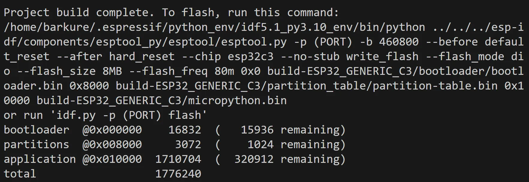
一共生成了三个固件:bootloader.bin、partition-table.bin、micropython.bin。
0x0、0x8000、0x10000 是三个固件对应的起始地址。
将这三个固件下载到 Windows,以备后续烧录。
三、烧录
使用乐鑫的 Flash 下载工具 将固件烧录到设备。
-
下载 flash_download_tool 后运行其中的可执行文件;
-
选择 ChipType 为 esp32-C3,点击 OK;
-
进入烧录页面,选择之前的三个固件,并填写对应的地址:
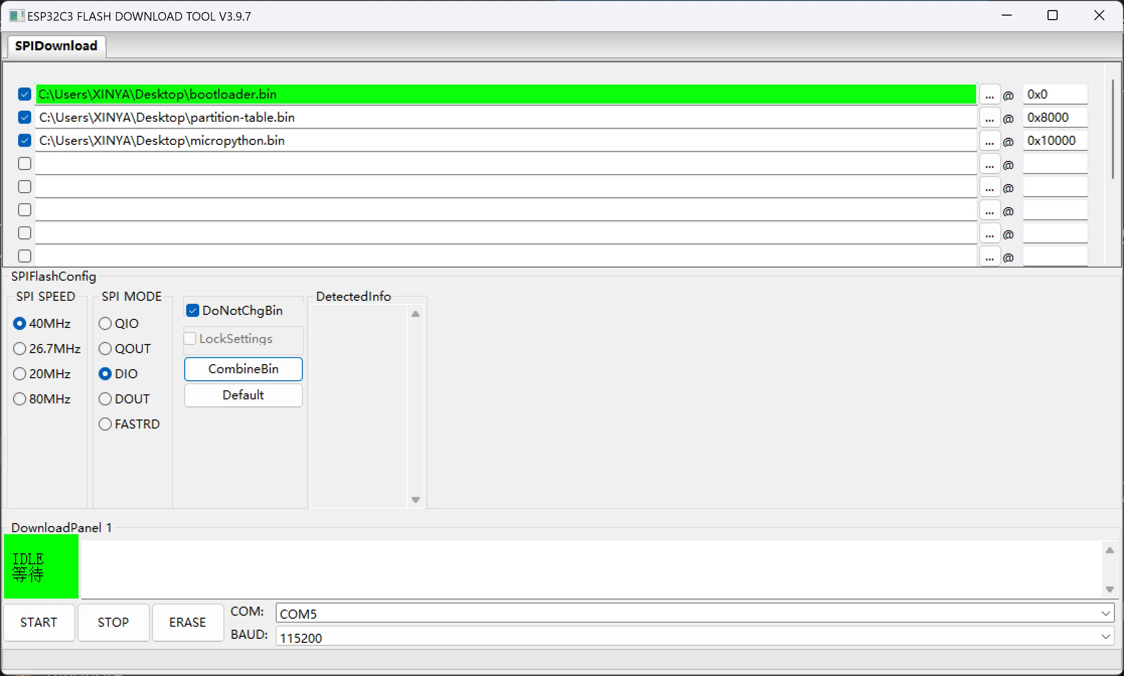
先点击 ERASE 擦除旧固件,成功后点击 START 刷入新固件。
四、亮屏测试
使用 Thonny 连接到开发板。

准备一张 240x320 大小的 bmp 格式的图片(即上图:Je.bmp)存到开发板的根目录,新建一个文件输入下面的内容:
from machine import Pin, SPI
import st7789
import time
import framebuf

# 初始化 SPI 接口
spi = SPI(1, baudrate=26666666, polarity=1, sck=Pin(3), mosi=Pin(5))

# 初始化 ST7789 屏幕
tft = st7789.ST7789(spi, 240, 320, dc=Pin(6, Pin.OUT), cs=Pin(4, Pin.OUT), inversion=True, rotation=90, options=0)
backlight = Pin(2, Pin.OUT)

tft.init()
backlight.value(0)  # 打开背光
tft.fill(st7789.WHITE)

# 显示 BMP 图片
def display_bmp(filename):
    with open(filename, 'rb') as f:
        if f.read(2) == b'BM':  # BMP 文件头
            f.read(8)  # 忽略文件大小和保留字
            offset = int.from_bytes(f.read(4), 'little')
            f.read(4)  # 忽略头信息大小
            width = int.from_bytes(f.read(4), 'little')
            height = int.from_bytes(f.read(4), 'little')
            if width > tft.width() or height > tft.height():
                raise ValueError("Image too large for display")

            f.read(offset - 26)  # 跳过其余的头信息

            for row in range(height):
                for col in range(width):
                    b, g, r = f.read(3)  # 读取 RGB 颜色
                    # 转换为 RGB565 格式
                    color = ((r & 0xF8) << 8) | ((g & 0xFC) << 3) | (b >> 3)
                    tft.pixel(col, height - 1 - row, color)

# 显示图片
display_bmp('/Je.bmp')

# 保持显示,直到手动重置
while True:
    time.sleep(1)
保存为 main.py 后运行:
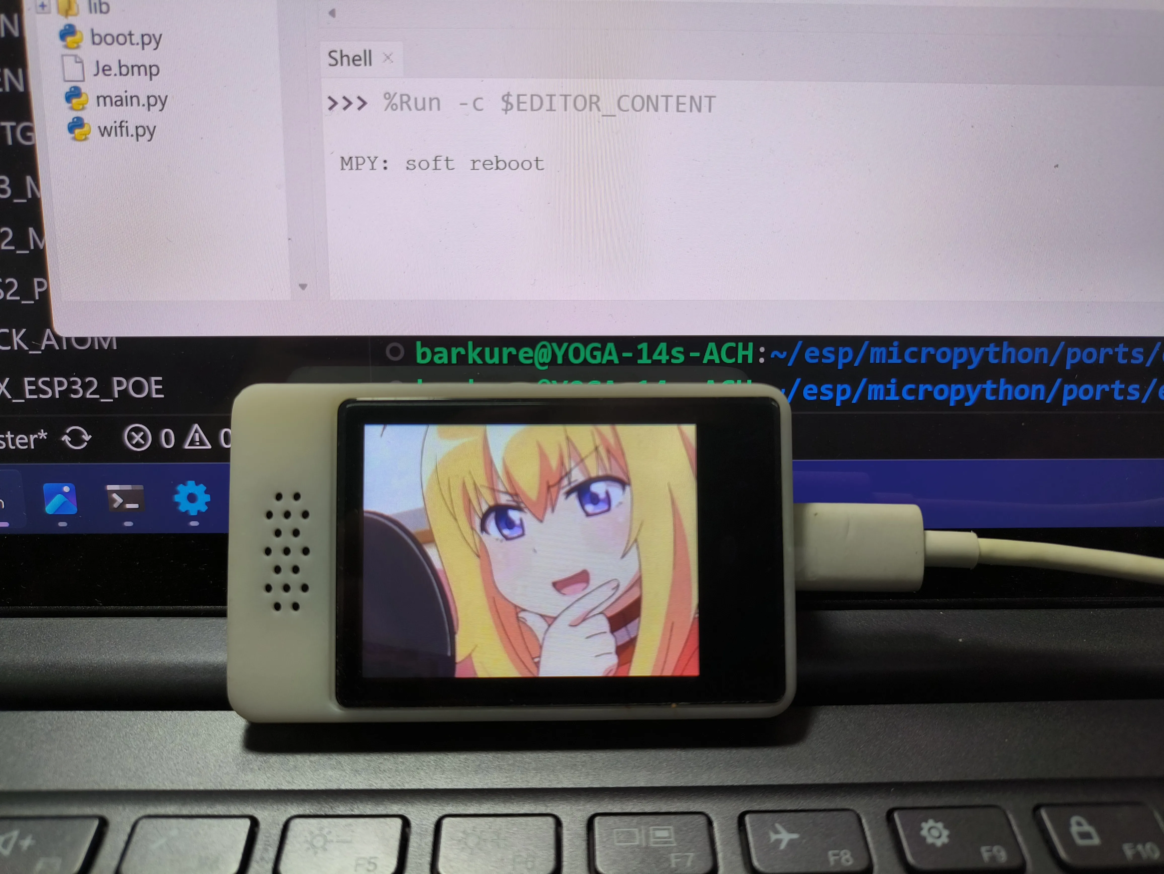
成功点亮!